|
|
UDDI Spec TC |


UDDI Version 2.03 Replication Specification
UDDI Committee Specification, 19 July 2002
Document identifier:
Replication_v2
Location:
http://uddi.org/pubs/Replication-V2.03-Published-20020719.htm
Latest version:
http://uddi.org/pubs/Replication_v2.htm
Editors:
Luc Clément, Microsoft
Contributors:
Robert Atkinson, Microsoft
Rainer Brendle, SAP
Pat Conley, Verisign
Shel Finkelstein, Sun
Tom Glover, IBM
Dan Guinan, Verisign
Andrew Hately, IBM
Yin Leng Husband, HP
Alan Karp, HP
Wooyoung Kim, HP
Christopher Kurt, Microsoft
Nicolai Jordt, SAP
Barbara McKee, IBM
Joel Munter, Intel
Andrew Nielsen, HP
Christian R Thomas, Intel
Acknowledgements:
The UDDI Spec TC recognizes the contributions of other participants from the UDDI.org Working Group:
Srikrishna Guttikonda, Ariba
UDDI Business Registry Operators Council
Abstract:
This document describes the data replication process and programmatic interface required to achieve complete data replication between UDDI Operators.
Status:
This specification has attained the status of OASIS Standard.
Committee members should send comments on this Committee Specification to the uddi-spec@lists.oasis-open.org list. Others should subscribe to and send comments to the uddi-spec-comment@lists.oasis-open.org list. To subscribe, send an email message to uddi-spec-comment-request@lists.oasis-open.org with the word "subscribe" as the body of the message.
For information on whether any intellectual property claims have been disclosed that may be essential to implementing this Committee Specification, and any offers of licensing terms, please refer to the Intellectual Property Rights section of the UDDI Spec TC web page (http://www.oasis-open.org/committees/uddi-spec/).
Copyrights
Copyright © 2001-2002 by Accenture, Ariba, Inc., Commerce One, Inc., Fujitsu Limited, Hewlett-Packard Company, i2 Technologies, Inc., Intel Corporation, International Business Machines Corporation, Microsoft Corporation, Oracle Corporation, SAP AG, Sun Microsystems, Inc., and VeriSign, Inc. All Rights Reserved.
Copyright © OASIS Open 2002-2003. All Rights Reserved.
Contents
2.1 Nodes, the Operator Cloud, and the UDDI Service
3.1 Replication Configuration File
3.2 Configuration of Each Operator
3.3 Control of the Node-to-node Communication Graph
4.1.1 notify_changeRecordsAvailable Message.
4.1.2 get_changeRecords Message
4.1.4 get_HighWaterMarks Message
4.2 Bug detection and Processing
4.2.1 Case 1: Invalid record validation
4.2.2 Case 2: Invalid interim representation
4.2.3 Case 3: Invalid generation
4.3.5 changeRecordPublisherAssertion
4.3.6 changeRecordDeleteAssertion
4.3.7 changeRecordCustodyTransfer
4.3.8 changeRecordAcknowledgment
5 Bringing New UDDI Operators Online
6 Checking and Validation of Replicated Data
6.2 Validity Checking and Enforcement
9.1.1 UDDI Specifications and documents
9.1.2 Standards and other Specifications
Appendix A: Miscellaneous Replication Example
Appendix B: Miscellaneous Replication Configuration Example
Appendix C: Non-normative – Cycle of Cycles Topology
This document is one piece of the set of specifications that support the Universal Description, Discovery and Integration (UDDI) specifications. This document describes the data replication process and programmatic interface required to achieve complete data replication between UDDI Operators. The replication process makes use of Extensible Markup Language (XML) and a related technology called Simple Object Access Protocol (SOAP). SOAP is a specification for using XML in simple message-based exchanges.
The UDDI Version 2.0 Programmer’s Reference Specification provides a short introduction to the project and describes the public UDDI interfaces. This specification describes the interfaces required to perform all of the UDDI Operator to UDDI Operator communications.
The primary audiences for this specification are:
· Existing UDDI Business Registry Operators
· Prospective UDDI Business Registry Operators
· Prospective Private UDDI Operators that are interested in a replication protocol
Implementers will find information in this document that defines the required replication process protocol and recommended and required behaviors all UDDI Node Operators must implement as a part of their UDDI Services. The goal of these policies and behaviors is to ensure that the UDDI Service works smoothly, both for the user community as a whole, and for the individual operators.
The UDDI Version 2.0 Programmer's API Specification defines approximately 40 API messages that are used to perform inquiry and publishing functions against any UDDI-compliant Business Registry. This Replication Specification document also describes a set of API messages that must be supported by all UDDI Operators in addition to those messages specified within the API Specification. This document is also complementary to the UDDI Operators Specification.
Note: This document is a co-requisite to the UDDI XML Schema and to the UDDI Replication XML Schema document.
The keywords MUST, MUST NOT, REQUIRED, SHALL, SHALL NOT, SHOULD, SHOULD NOT, RECOMMENDED, MAY, and OPTIONAL, when they appear in this document, are to be interpreted as described in RFC 2119.
This section outlines the key concepts and includes in-depth technical descriptions involved within replication.
2.1 Nodes, the Operator Cloud, and the UDDI Service
There is an identified set of (operator) nodes involved in the operation of the UDDI Service. To the outside world, the cloud of Operator nodes should appear and act as a single service. Each Operator node within the UDDI Service will be identified within a Replication Configuration File. The contents and format of this configuration file are described later in this document.
An individual Operator node may be comprised of several physical computers but will be represented by one unique ID of type Universal Unique Identifier (UUID). Details specifying the format of the UUID can be found in the UUID Algorithm section in the UDDI Operators Specification. As is shown in the Replication Configuration file, one unique URL is specified to represent the replication point, soapReplicationURL for each Operator node.
A goal of UDDI replication is to ensure that, all nodes see all the changes that have originated at individual Operator nodes. An additional goal is that registry inquiries made at any Operator node within the UDDI Service yield results consistent to those made at any other Operator node within the UDDI Service. The response should be complete and sent to the caller as quickly as possible. This consistency is defined as a response comprised of the same businessEntities, businessServices, tModels, bindingTemplates, and publisherAssertions, sorted the same way. The consistency of the results is subject to any replication latencies.
Throughout this specification, when we are referring to aspects of the UDDI Service, we may refer to it as the UDDI Operator Cloud. This can be thought of as the collection of UDDI capabilities and services supported collectively by this set of Operators.
2.2 Data Custody
Each node has custody of a certain portion of the aggregate data managed by the UDDI Service. Each datum is in the custody of exactly one such Operator node. A datum can be a business entity, a business service, a binding template, a tModel, or an assertion within a business relationship. Changes to a datum in the UDDI Service can only be made at the node in whose custody the datum resides. Although Publishers initiate the changes by their inserts, updates, or deletes of the actual data, Operator nodes are said to “originate changes” for such data into the Replication stream.
The Operator node that is the custodian of a datum can be changed. The Change of Custody process utilizes a multi-step process and utilizes “replication” to accomplish the final steps within this process. The complete Change of Custody Process is defined within the UDDI Operators Specification.
2.3 Update Sequence Numbers
Each node shall maintain a strictly increasing register known as its Update Sequence Number (USN). The USN register must never decrease in value, even in the face of system crashes and restarts. The register must be sufficiently large such that register rollover is not a concern. For all Operator node to Operator node communications, Operators must implement a USN exactly 63 bits in size. Operator nodes must not rely on a USN value always increasing by exactly one. Gaps in an Operator node's USN sequence are explicitly permitted and are likely to occur in the face of system crashes and restarts.
While processing changes to the Registry all data must be ‘tagged’ with a unique USN register value. It is recommended that within an implementation, an Operator node would tag the new or updated record and then increment its USN register. This process would assure that the USN values remain unique.
Note that it is semantically meaningless to compare USNs that have been generated on different Operator nodes; only USNs generated on the same Operator node may be meaningfully compared to each other.
2.4 Change Records
When a publisher changes a specific datum at an Operator node, the Operator node will create a change record that describes the details of the change.[1] A datum can be a business entity, a business service, a binding template, a tModel, or a publisher assertion within a business relationship.
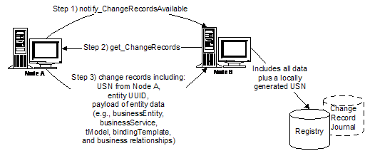
Each change record contains the following information:
· The UUID of the originating node on which the change record was initially created.
· An originating USN, with which the change record is tagged at its creation by its originating Operator node.
· A payload of data that conveys the semantics of the change in question. These shall be elaborated and fully specified later in this specification.
As a part of the replication process defined within this specification, change records are transmitted between Operator nodes. Each step of replication involves the transmission of such records from one Operator node to one other Operator node, say from Operator node M to Operator node N. As Operator node N receives change records from Operator node M, Operator node N tags each incoming record with a fourth piece of (Operator node-N-generated) information:
· A local USN.
Should the Operator node N elect to record its own change records within its Change Record Journal, the local USN and the originating USN values on the records are set to an identical USN value. Thus, all change records ever seen by a node can be time-ordered by sorting on their local USN.
As we shall see later, change records are always replicated to other nodes strictly in increasing order of the local USN of the node providing the changes. This property, together with the rules under which local USNs are assigned, provides the following guarantee: Suppose a publisher, whose data is held at node N, (that is, Node N is the custodian of that data) changes its data. Node N originates a change record c. Then it is guaranteed that any other node which receives change c will have previously received all changes which on node N had a local USN less than the local (and originating) USN of c. This, however, is true only of changes c that N originates. This is not true of arbitrary changes that N has seen from others.
This important cause and effect relationship is relied upon in several places in the design elaborated below, notably the algorithm by which information is ultimately deleted from the Service, and the algorithm by which custody of data is transferred from one operator to another.
2.5 Change Record Journal
Accurate replication of data throughout the UDDI Service relies on accurate and faithful creation, transmission, and retransmission of change records between all nodes of the UDDI Service. A change record originated by an Operator node is the authoritative document for information propagation. It is critical that change records are not inadvertently altered as they are conveyed from the originating Operator node through intermediate Operator nodes to reach other Operator nodes in the UDDI Service.
To that end, each Operator node should create and maintain as part of their internal implementation a change record journal that explicitly records verbatim the XML text of change records as they are received from other Operator nodes. This journaling may be performed before or after standard XML parsing of the change record. It is understood that standard XML parsing may remove leading and trailing white space. It is believed that this journaling will significantly enhance the overall quality of the UDDI Service.
Implementers may find it convenient to also place their own change records in their change record journal.
2.6 High Water Mark Vector
Each node maintains state information as a high water mark vector that contains the USN of the most recent change record that has been successfully processed from each operator. This vector has one entry for each node in the replication graph. Each entry contains the following information
· operatorNodeID, which contains the UUID of a node in the replication graph, and
· originatingUSN, which contains the operatorNodeID-specific USN of the most recent change that originated on operatorNodeID and which node N has successfully consumed. Since changes originating on a given node are always consumed in order, this will necessarily be the largest USN of any M-originating change that N has successfully consumed.
2.7 Time-based Elements
Instants of time are referenced throughout UDDI replication and within the Auditing process. These time stamps ensure that time changes were recorded consistently and are in the XML timeInstant format. See http://www.w3.org/TR/xmlschema-2 for the definition.
References to these time instants are found within the Replication Configuration File as well as many of the Audit requirements. The sections describing these data will detail more specific uses for the time instants they contain.
The replication of UDDI data is governed by information maintained within a UDDI Replication Configuration file. This file includes sufficient information to uniquely identify each Operator node within the UDDI Service. The custodian of the Replication Configuration File is the UDDI Operators Council. Each Operator must specify at least one contact as described below.
3.1 Replication Configuration File
The replication configuration of the UDDI Service is specified by an XML file kept at the location
https://www.uddi.org/operator/ReplicationConfiguration.xml
The XML schema definition describing the replicationConfiguration element is shown below. The root element of an instance document of this XML schema must be a replicationConfiguration element as defined in the UDDI v2 replication schema:[2]
<element name="replicationConfiguration">
<complexType>
<sequence>
<element name="serialNumber" type="repl:USN_type"/>
<element name="timeOfConfigurationUpdate" type="timeInstant"/>
<element name="councilContact">
<complexType>
<sequence>
<element ref="api_v2:contact"/>
</sequence>
</complexType>
</element>
<element ref="repl:operator" minOccurs="0" maxOccurs="unbounded"/>
<element name=”maximumTimeToSyncRegistry” type=”integer” minOccurs=”0” maxOccurs=”1”/>
<element name=”maximumTimeToGetChanges” type=”integer”/>
<element ref="repl:communicationGraph" minOccurs="0" maxOccurs="1”/>
</sequence>
</complexType>
</element>
A replicationConfiguration contains a serialNumber which is increased by at least one each time the published configuration is updated or changed. For the convenience of human users, the timeOfConfigurationUpdate identifies the time of the last update. The formatting of the timeOfConfigurationUpdate element is described later in this document. The councilContact identifies a party in the UDDI Operators Council who maintains and updates the Replication Configuration File.
Two new elements have been introduced in Version 2. The first new element, maximumTimeToSyncUBR, allows for the specification of when (in hours) a change made at any single node in the UDDI Business Registry is expected to be visible at all nodes within the UDDI Business registry. The second new element, maximumTimeToGetChanges, allows for the specification of the maximum amount of time (in hours) that an individual node may wait to request changes.
The Management of the Replication Configuration file is completely specified within the UDDI Operators Specification document. Members of the Operators Council must manage any and all changes to the contents of the Replication Configuration File.
The remaining elements in a replicationConfiguration are a list of the operators and established paths of communication between the Operator nodes. The communication paths and general replication topology considerations are discussed later in this document.
When the master configuration file is updated, existing operators are informed of the update by an out-of-band means not defined in this specification.
3.2 Configuration of Each Operator
Each current UDDI operator within the Service is identified with an operator element in the replicationConfiguration:
<element name="operator">
<complexType>
<sequence>
<element name="operatorNodeID" type="repl:operatorNodeID_type"/>
<element name=”operatorStatus” type=”repl:operatorStatus_type”/>
<element ref="api_v2:contact" maxOccurs="unbounded"/>
<element name="operatorCustodyName" type="repl:operatorName_type"/>
<element name="soapReplicationURL" type="anyURI"/>
<element name="certIssuerName" type="string"/>
<element name="certSubjectName" type="string"/>
<element name="certificate" type="base64Binary" minOccurs="0" maxOccurs="unbounded"/>
</sequence>
</complexType>
</element>
<simpleType name="operatorName_type" >
<annotation>
<documentation>For use in ‘operator’ attributes of businessEntities, etc.</documentation>
</annotation>
<restriction base=”string”/>
</simpleType>
<simpleType name="operatorStatus_type" >
<annotation>
<documentation>A UDDI Service-Level Operator Readiness state value</documentation
</annotation>
<restriction base=”NMTOKEN”>
<enumeration value=”new” />
<enumeration value=”normal” />
<enumeration value=”resigned” />
</restriction>
</simpleType>
<simpleType name="operatorNodeID_type" >
<annotation>
<documentation>A UUID in DCE String Format</documentation>
</annotation>
<restriction base=”string”>
<length value=”36” />
</restriction>
</simpleType>
The operatorNodeID contains a UUID that is used to uniquely identify this operator throughout the UDDI Service. The contact or contacts listed provide information about humans who should be contacted in the face of administrative and technical situations of various sorts. The operatorCustodyName is the name used for the operator in ‘operator’ attributes of businessEntitys, tModels, and the like.
3.2.1 SOAP Configuration
In UDDI v2, node-to-node replication communication is carried out by means of SOAP messages and responses. The soapReplicationURL indicated in the operator element indicates where such messages should be sent to communicate with a given operator node. Specifically, in order to carry out a message invocation of type X with a given operator, a message is POST’ed to the URL documented within the Replication Configuration file. The type of message is indicated on the POST line. It is required (see below) that an operator’s soapReplicationURL indicate a secure HTTP connection.
For example, in order to invoke the message notify_changeRecordsAvailable to the operator whose soapReplicationURL is https://uddi.microsoft.com/SOAP/, an HTTPS POST beginning with the following should be made:
POST /SOAP HTTP/1.1
Host: uddi.microsoft.com
Content-Type: text/xml; charset=”utf-8”
Content-Length: nnnn
SOAPAction: “”
<?xml verson=”1.0” encoding=”UTF-8” ?>
<Envelope xmlns=”http://schemas.xmlsoap.org/soap/envelope/” >
<Body>
<notify_changeRecordsAvailable>
…
For more information regarding the use of SOAP within API messaging in UDDI, please refer to the UDDI Version 2.0 Programmer’s Reference Specification.
3.2.2 Security Configuration
Authentication of replication communication between nodes is carried out just as was done in UDDI v1.[3] Specifically, each node is required to be able to operate as both a Transport Layer Security (TLS) 1.0[4] client and a TLS 1.0 server with at least the following set of cipher suites:
· RC4 with 40-bit encryption and MD5 message authentication
· RC2 with 40-bit encryption and MD5 message authentication.
To effect this authentication, each operator is required to obtain an X.509v3 certificate. Full details of this certificate and the Certificate Authorities (CAs) can be found within the UDDI Operators Specification.
Operators must identify in their operator element the certificate they obtain from one of these CAs. Specifically, they must list the contents of the so-called ‘issuer name’ and ‘subject name’ attributes of the certificate in the (respectively) certIssuerName and certSubjectName elements of their operator element. If they wish, operators may place the full X.509v3 certificate they have obtained in a certificate element of their operator; this provides a handy and convenient place by which certificates can be (manually) located as new operators are brought online.
When communicating with another operator, each operator must validate the replication communications against this operator authentication identification found in the master configuration file. Certificate credentials presented over TLS must be validly used cryptographically, and, in addition, must match the (certIssuerName, certSubjectName) pair of one of the configured operators.
3.2.3 Examples
The following are examples of valid operator elements:
This first example shows an operator, “Microsoft Corporation,” with four separate Contacts.
<operator>
<operatorNodeID>3bbef815-df6a-484a-9d9f-afe470913566</operatorNodeID>
<operatorStatus>normal<operatorStatus>
<api_v2:contact useType="Customer Support">
<api_v2:personName>Microsoft UDDI Customer Support</api_v2:personName>
<api_v2:email>uddiExample@microsoft.com</api_v2:email>
</api_v2:contact>
<api_v2:contact useType="Operations Partner Support">
<api_v2:personName>Operations and Partner Support</api_v2:personName>
<api_v2:phone useType="Voice">800.555.8352 pin 1845992</api_v2:phone>
<api_v2:email>uddiOpsExample@microsoft.com</api_v2:email>
</api_v2:contact>
<api_v2:contact useType="Primary Contact for Critical Issues and Operations Management">
<api_v2:personName>Angela Mills</api_v2:personName>
<api_v2:phone useType="Voice">425.555.3447</api_v2:phone>
<api_v2:phone useType="Cellular">425.555.7048</api_v2:phone>
<api_v2:email>uddiAngela@microsoft.com</api_v2:email>
</api_v2:contact>
<api_v2:contact useType="Primary Contact for Critical Replication Issues">
<api_v2:personName>Joe Admin</api_v2:personName>
<api_v2:phone useType="Voice">425.555.3447</api_v2:phone>
<api_v2:phone useType="Cellular">425.555.7048</api_v2:phone>
<api_v2:email>uddiReplication@microsoft.com</api_v2:email>
</api_v2:contact>
<api_v2:contact useType="Secondary Contact for non-operational issues">
<api_v2:personName>Chris Kurt</api_v2:personName>
<api_v2:phone useType="Voice">425.555.5589</api_v2:phone>
<api_v2:phone useType="Cellular">630.555.8170</api_v2:phone>
<api_v2:email>uddiChris@microsoft.com</api_v2:email>
</api_v2:contact>
<operatorCustodyName>Microsoft Corporation</operatorCustodyName>
<soapReplicationURL>https://uddi.microsoft.com/SOAP/</soapReplicationURL>
<certIssuerName>OU=Secure Server Certification Authority, O=RSA Data Security, Inc., C=US</certIssuerName>
<certSubjectName>CN=UDDI.MICROSOFT.COM, OU=UDDI production site, O=Microsoft, L=Redmond, S=Washington, C=US</certSubjectName>
</operator>
This example describes an operator, “www.ibm.com/services/uddi,” with one valid Contact.
<operator>
<operatorNodeID>1b51ffea-9101-43d0-bab9-4c5791e102b1</operatorNodeID>
<operatorStatus>normal<operatorStatus>
<api_v2:contact useType="Operator Contact">
<api_v2:personName>Tom Glover</api_v2:personName>
<api_v2:phone useType="Voice">416.555.4220</api_v2:phone>
<api_v2:phone useType="Fax">416.555.4414</api_v2:phone>
<api_v2:email>uddiTom@us.ibm.com</api_v2:email>
</api_v2:contact>
<operatorCustodyName>www.ibm.com/services/uddi</operatorCustodyName>
<soapReplicationURL>https://www-300.ibm.com/services/uddi/replication/</soapReplicationURL>
<certIssuerName>CN=Equifax Secure E-Business CA-2, O=Equifax Secure Inc, C=US</certIssuerName>
<certSubjectName>EmailAddress=ibmuddi@us.ibm.com, CN=www.ibm.com/services/uddi, OU=IBM Global Services-Boulder, O=IBM Global Services, C=US</certSubjectName>
</operator>
This example describes an operator, “ariba,” with one valid Contact.
<operator>
<operatorNodeID>3d0bd27e-3df3-42d6-98ec-75a7a409bcaf </operatorNodeID>
<operatorStatus>normal<operatorStatus>
<api_v2:contact useType="Operator Contact">
<api_v2:personName>Ariba Network Operations</api_v2:personName>
<api_v2:phone useType="Voice">650-555-6200</api_v2:phone>
<api_v2:email>uddiOpsExampple@ariba.com</api_v2:email>
</api_v2:contact>
<operatorCustodyName>ariba</operatorCustodyName>
<soapReplicationURL>https://service.ariba.com/UDDIProcessor.aw/ad/</soapReplicationURL>
<certIssuerName>OU=Secure Server Certification Authority, O=RSA Data Security, Inc., C=US</certIssuerName>
<certSubjectName>CN=service.ariba.com, OU=Terms of use at www.verisign.com/RPA (c)99, OU=Ariba.com Network, O=Ariba Technologies, L=Sunnyvale, S=California, C=US</certSubjectName>
</operator>
3.3 Control of the Node-to-node Communication Graph
The master configuration file provides an optional means by which the inter-node replication traffic can be controlled and administered. This is done with the use of a communicationGraph element:
<element name="communicationGraph">
<complexType>
<sequence>
<element name="node" type="repl:operatorNodeID_type" maxOccurs="unbounded"/>
<element name="controlledMessage" type="string" maxOccurs="unbounded"/>
<element name="edge" minOccurs="0" maxOccurs="unbounded">
<complexType>
<sequence>
<element name="message" type="string" maxOccurs="unbounded"/>
<element name="messageSender" type="repl:operatorNodeID_type"/>
<element name="messageReceiver" type="repl:operatorNodeID_type"/>
<element name="messageReceiverAlternate" type="repl:operatorNodeID_type" minOccurs="0" maxOccurs="unbounded"/>
</sequence>
</complexType>
</element>
</sequence>
</complexType>
</element>
The communicationGraph element begins by explicitly listing the ID’s of the nodes currently involved in the overall replication communication. Each listed node ID must be operatorNodeID of some configured operator. At first glance, this listing of nodes might appear redundant with the prior listing of the operator elements; however, its presence carefully separates the control of communication with a node from other aspects of its configuration, such as the provision and dissemination of its security credentials.
Following the listing of nodes is the set of messages that this communication graph is intended to administer the control of. If a message element name is listed here, then such messages shall only be sent between nodes that are listed in the subsequent edges of the graph. In contrast, no communication restrictions are imposed on “replication protocol” message names not listed here.
After the nodes involved in replication communication are identified, the graph edges imposed on those nodes are listed. All node id’s listed in an edge must have been previously listed as valid in a node. Each edge in the graph is a directed edge, and indicates that only messages of the type explicitly listed as a valid message for the edge may be sent from the indicated messageSender to the messageReceiver. Restricted two-way communication between nodes must, if desired, be listed as a pair of edges with opposing directionality. A given directed edge may be listed at most once: for each edge, the pairing (messageSender, messageReceiver) must be unique over the entire set of edges of the graph.
For each directed edge, an ordered sequence of zero or more alternate, backup edges may be listed. Should a communications failure prevent message communication over the indicated primary edge, the backup edges may be tried in order until communication succeeds.
In the absence of a communicationGraph element from the replication Configuration file (recall that it is optional), all listed operator nodes may send any and all messages to any other listed operator.
The following is an example of a simple communicationGraph that restricts the invocation of get_changeRecords messages to a unidirectional-ring amongst a set of four nodes. In operational practice, it is expected that this get_changeRecords message will typically be the only UDDI replication message where communication restrictions are imposed. The introduction of communication restrictions on the notify_changeRecordsAvailable messages between operating nodes is not expected to be commonplace.
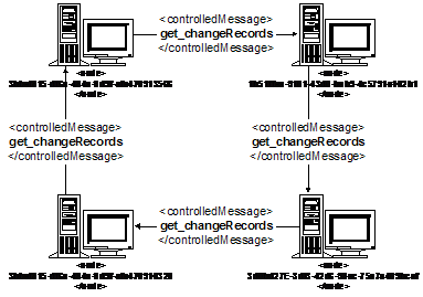
The communication graph described in the following example represents a spanning cycle topology. This is one of many possible topologies supported within this replication framework.
<communicationGraph>
<node>3bbef815-df6a-484a-9d9f-afe470913566</node>
<node>1b51ffea-9101-43d0-bab9-4c5791e102b1</node>
<node>3d0bd27e-3df3-42d6-98ec-75a7a409bcaf</node>
<node>3bbef815-df6a-484a-9d9f-afe470910320</node>
<controlledMessage>get_changeRecords</controlledMessage>
<edge>
<message>get_changeRecords</message>
<messageSender>3bbef815-df6a-484a-9d9f-afe470913566</messageSender>
<messageReceiver>1b51ffea-9101-43d0-bab9-4c5791e102b1</messageReceiver>
</edge>
<edge>
<message>get_changeRecords</message>
<messageSender>1b51ffea-9101-43d0-bab9-4c5791e102b1</messageSender>
<messageReceiver>3d0bd27e-3df3-42d6-98ec-75a7a409bcaf </messageReceiver>
</edge>
<edge>
<message>get_changeRecords</message>
<messageSender>3d0bd27e-3df3-42d6-98ec-75a7a409bcaf </messageSender>
<messageReceiver>3bbef815-df6a-484a-9d9f-afe470910320</messageReceiver>
</edge>
<edge>
<message>get_changeRecords</message>
<messageReceiver>3bbef815-df6a-484a-9d9f-afe470910320</messageReceiver>
<messageReceiver>3bbef815-df6a-484a-9d9f-afe470913566</messageReceiver>
</edge>
</communicationGraph>
Replication processing consists of the Notification of changes that are available and then the subsequent “pulling” of changes from one of the Operator nodes within the Service. To improve the process of Replication as compared with Version 1, an Operator node can advertise that changes are available at that node. The advertisement of changes available includes sufficient information so that another Operator node within the Service can determine if and when it should pull the changes from the offering Operator node to itself for replication processing.
Replication should be configured so that in the absence of failures, changes propagate throughout the UDDI Service within a set amount of time. This requirement means that get_changeRecords requests may have to be sent in some scheduled manner.
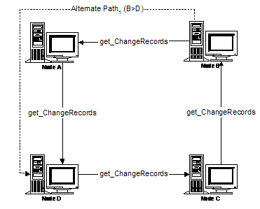
For example, assume that the Communications Graph is a cycle of 4 operator nodes (A, B, C, and D) such that D places get_changeRecords request to C (D>C), C>B, B>A, and then finally A>D.
In this example, A starts the Replication process. Periodically, A generates a timer event and notifies B of its highWaterMark vector; if necessary, B issues a get_changeRecords request to A, and then sends C its highWaterMark vector. This continues around the cycle (B>A, C>B, D>C, A>D), but doesn't stop there. B has not received any changes from C or D for the current period, and C has not received any changes from D.
So A continues this algorithm around the cycle again (B>A, C>B, D>C). At this point, all changes that existed when A handled its timer event have been circulated to all nodes. (Subsequent changes may have also been propagated, which is okay.)
Please refer to Appendix C for a non-normative discussion about a variation on the topology just discussed.
Operators may find it advantageous to do local optimizations of changes prior to replicating the changes throughout the UDDI Service. Any local optimizations performed must be invisible to other operator nodes.
4.1 Replication Messages
As was previously mentioned UDDI Version 2 replication is carried out solely through the exchange of SOAP messages between nodes rather than the maintenance and transfer of files as was done in UDDI Version 1; these messages are specified below. Various details of several aspects of SOAP usage are the same as those discussed in the UDDI Version 2.0 Programmer’s Reference Specification, Appendix B.
Processing an inbound replication message may fail due to a server internal error. The common behavior for all error cases is to return an ‘E_fatalError’ error code. Error reporting SHALL be that specified by Section 5.1.2 Error reporting with the dispositionReport element of the UDDI Programmer’s API Reference specification as follows:
<?xml version="1.0" encoding="UTF-8" ?>
<Envelope xmlns="http://schemas.xmlsoaporg.org/soap/envelope/">
<Body>
<Fault>
<faultcode>Server</faultcode>
<faultstring>Server Error</faultstring>
<detail>
<dispositionReport xmlns="urn:uddi-org:api_v2">
<result errno="109xx">
<errInfo errCode=“E_fatalError">The changeRecord type
is not unrecognized: XYZ</errInfo>
</result>
</dispositionReport>
</detail>
</Fault>
</Body>
</Envelope>
4.1.1 notify_changeRecordsAvailable Message
A means is provided by which nodes can inform other nodes that they have more change records newly available for consumption by replication. This provides a non-polling means by which replication can be initiated, potentially reducing the latency of the dissemination of changes throughout the set of UDDI operators.
At an interval deemed appropriate by the operator after the origination of new change records within its node, it should invoke this message on each of the other nodes with which it may legally communicate this message according to the currently configured communicationGraph.
<element name="notify_changeRecordsAvailable">
<complexType>
<sequence>
<element name="notifyingNode" type="repl:operatorNodeID_type"/>
<element name="changesAvailable" type="repl:highWaterMarkVector_type"/>
</sequence>
</complexType>
</element>
A node MUST respond with a disposition report with the E_success error code when a valid notify_changeRecordsAvailable message is received. Success reporting SHALL be that specified by Section 5.1.2 Error reporting with the dispositionReport element of the UDDI Programmer’s API Reference as follows:
<?xml version="1.0" encoding="UTF-8" ?>
<Envelope xmlns="http://schemas.xmlsoaporg.org/soap/envelope/">
<Body>
<dispositionReport xmlns="urn:uddi-org:api_v2" >
<result errno="0" >
<errInfo errCode=“E_success" />
</result>
</dispositionReport>
</Body>
</Envelope>
The parameter to the notify_changeRecordsAvailable message indicates that the notifyingNode has available the indicated set of changes for request via get_changeRecords. When sending this message, a node shall provide a high-water mark vector identifying what changes it knows to exist both locally and on other nodes with which it might have had communications. This get_changeRecords message, like the other messages described herein, is subject to communication restrictions imposed by the configured communicationGraph. Typically, no such restrictions are present for the notify_changeRecordsAvailable message.
<complexType name="highWaterMarkVector_type">
<sequence>
<element name="highWaterMark" type="repl:changeRecordID_type" minOccurs="0" maxOccurs="unbounded"/>
</sequence>
</complexType>
<complexType name="changeRecordID_type">
<sequence>
<element name="nodeID" type="repl:operatorNodeID_type"/>
<element name="originatingUSN" type="repl:USN_type"/>
</sequence>
</complexType>
Operators must perform a get_changeRecords replication message within the time frame defined by the value of the maximumTimeToGetChanges element defined within the Replication Configuration File. Thus, change data can always be propagated throughout the UDDI Service within a finite amount of time, while at the same time changes will often propagate quickly.
The following is an example of a notify_changeRecordsAvailable message:
<notify_changeRecordsAvailable>
<notifyingNode>1b51ffea-9101-43d0-bab9-4c5791e102b1</notifyingNode>
<changesAvailable>
<highWaterMark>
<nodeID>1b51ffea-9101-43d0-bab9-4c5791e102b1</nodeID>
<originatingUSN>123</originatingUSN>
</highWaterMark>
<highWaterMark>
<nodeID>3bbef815-df6a-484a-9d9f-afe470913566</nodeID>
<originatingUSN>241</originatingUSN>
</highWaterMark>
<highWaterMark>
<nodeID>3d0bd27e-3df3-42d6-98ec-75a7a409bcaf</nodeID>
<originatingUSN>193</originatingUSN>
</highWaterMark>
</changesAvailable>
</notify_changeRecordsAvailable>
4.1.2 get_changeRecords Message
The get_changeRecords message is used to initiate the replication of change records from one node to another. The caller, who wishes to receive new change records, provides as part of the message his current high water mark vector. This is used by the data source Operator node to determine what change records satisfy the caller’s request.
<element name="get_changeRecords">
<complexType>
<sequence>
<element name="requestingNode" type="repl:operatorNodeID_type"/>
<element name="changesAlreadySeen" type="repl:highWaterMarkVector_type" minOccurs="0"/>
<choice minOccurs="0">
<element name="responseLimitCount" type="integer"/>
<element name="responseLimitVector" type="repl:highWaterMarkVector_type"/>
</choice>
</sequence>
</complexType>
</element>
The requestingNode element indicates the identity of the calling node.
The changesAlreadySeen element, if present, indicates changes from each node that the requestor has previously successfully processed, and thus which should not be resent to him, if possible. A caller may place an upper bound on the number of change records he wishes to receive in response to this message by either providing a integer responseLimitCount, or, using responseLimitVector, indicating for each node in the graph the first change originating there that he does not wish to be returned.
More specifically, the particular change records that are worthwhile to return are determined by the recipient by comparing the USNs in the caller’s high water mark vector with the originating USNs of each of the changes the recipient seen from others or generated itself. The recipient should only return changes whose originating USNs greater than those listed in the changesAlreadySeen highWaterMarkVector and less than the limit required by either the responseLimitCount or the responseLimitVector.
In nodes that support pre-bundled replication responses, the recipient of the get_changeRecords message may return more change records than requested records by the caller. In this scenario, the caller must also be prepared to deal with such redundant changes where a USN is less than the USN specified in the changesAlreadySeen highWaterMarkVector.
The response to a get_changeRecords message is a changeRecords element. Under all circumstances, all change records returned therein by the message recipient must be returned sorted in increasing order according to the recipient’s local USN.
<element name="changeRecords">
<complexType>
<sequence>
<element ref="repl:changeRecord" minOccurs="0" maxOccurs="unbounded"/>
</sequence>
</complexType>
</element>
The changeRecord element is defined later in this specification.
4.1.3 do_ping Message
This simple UDDI API message provides the means by which the current existence and replication readiness of a node may be obtained.
<element name="do_ping">
</element>
The response to this message must contain the operatorNodeID element of the pinged node.
<element name="operatorNodeID" type="repl:operatorNodeID_type"/>
</element>
4.1.4 get_HighWaterMarks Message
This API is called from one node to another node within the registry without any arguments. The message returns the latest known highWaterMarks for all of the nodes known by the node receiving the call. The schema for the new API message is:
<element name="get_highWaterMarks">
<complexType>
<sequence/>
</complexType>
</element>
The return from this is:
<element name="highWaterMarks" type="repl:highWaterMarkVector_type"/>
Where highWaterMarkVector_type is defined as:
<complexType name="highWaterMarkVector_type" final="restriction">
<sequence>
<element name="highWaterMark" type="repl:changeRecordID_type"
minOccurs="0" maxOccurs="unbounded"/>
</sequence>
</complexType>
Where changeRecordID_type is defined as:
<complexType name="changeRecordID_type" final="restriction">
<sequence>
<element name="nodeID" type="repl:operatorNodeID_type"/>
<element name="originatingUSN" type="repl:USN_type"/>
</sequence>
</complexType>
If the highest originatingUSN for a specific node within the registry is not known, then a node responding to a getHighWaterMark MUST return a highWaterMark for that node with an originatingUSN of 0 (zero).
e.g.:
<highWaterMark>
<nodeID>3bbef815-df6a-484a-9d9f-afe470910320</nodeID>
<originatingUSN>0</originatingUSN>
</highWaterMark>
4.2 Bug detection and Processing
While replication errors are expected to happen rarely, mechanisms must be in place to detect, deal with, and help manage the correction of such problems.
Throughout this section we will consider a UDDI Service consisting of 4 operator nodes (A, B, C, and D) configured in a cyclic replication pattern such that D places get_changeRecords requests to C (D>C), C>B, B>A, A>D. In addition to each node’s primary replication edge a set of alternate edges have been defined for each node which, in case of difficulty, permits it to bypass each upstream node in turn (i.e. B has two secondary edges: B>D and B>C. For clarity, only one is shown below).
Asserting an invalid change record:
In all of the cases below we assume that the following steps are executed, in the order listed:
1. A Publisher of data held in custody at Node D saves changes to that data
2. Node D originates a change record x.
3. Node A issues a get_changeRecords request to node D and successfully processes the change record set containing x which D issued in response.
4. Node B issues a get_changeRecords request to node A and processes the change record set which node A issued in response. During processing of the change record set node B encounters x and is unable to validate it.
When node B is unable to validate x it is required to signal that it has encountered a change record that it considers invalid (see the section entitled “Checking and Validation of Replicated Data” for a precise definition of what it means for a change record to be ‘invalid’). It does this by communicating to all of the UDDI Service node operators. The communication must include the following:
· The originating Node’s USN Value
· The reporting Operator Node ID
· The Originating Node ID
· The Replication operation type being processed (i.e., changeRecordPayload_type)
· The UUID of the datum being processed
· The type of datum being processed (i.e., businessEntity, businessService, tModel, etc.)
In addition node B must refuse to accept x from node A (i.e. it must not add x to its journal, must not process x into its registry, and must not update its high water mark vector to reflect processing of x) and must not consider x to be successfully processed. Recall that node A is required to deliver records ordered by local USN and node B is required to consume records in the order they are provided. As a consequence, node B will for the moment be unable to accept any other new records from node A. Note that Node B may have successfully processed other change records from the change record set it received from node A. If those change records preceded x, then they are unaffected by the issues associated with x.
This design avoids polluting node B with data that it knows to be invalid, while preserving the important ordering guarantee of change propagation upon which other replication semantics rely.
UDDI Service Investigation and Correction:
Once node B has asserted the existence of an invalid change record the UDDI Service operators must take remedial action. The investigation of node B's assertion regarding x may have a number of outcomes. Those we expect are documented in the cases below.
The following change records are used in these cases:
x: a changeRecordNewData message created by D that B asserts is invalid.
y: a changeRecordCorrection message created by D containing x’, a corrected payload for x.
z: a changeRecordNewData message created by D containing current payload for x.
4.2.1 Case 1: Invalid record validation
The UDDI Service operators may determine that node B’s assertion that x is invalid may be a result of overly aggressive checking and validation in B’s UDDI implementation. In this case:
· Node B will be required to change its code,
· Node B will continue to participate in replication cycles, retrying propagation of x from A to B in each cycle until the code changes are deployed and x is processed successfully.
4.2.2 Case 2: Invalid interim representation
The assertion by node B that x is incorrect may reflect incorrect handling of x by interim node A (recall that x is replicated first from node D to node A, then from node A to node B). Note that the originating node D contains a valid x. In these cases:
· Node A will be required to change its code.
· Node D will be required to generate y and z.
· Node A will continue to participate in replication, processing y (annotating x in its journal to refer to x’ in y) and z in one or more change record sets from node D,
· Node B will continue to participate in replication in subsequent cycles. In each it will attempt to propagate x from node A, then begin to exercise its alternate edges, descending one additional edge each cycle (i.e. in cycle (n+1) it will attempt to replicate using B>A and B>D). At some point node B may process a valid x from an alternate node, in these instances, node B will later process y (annotating x to point to x’ in y) and z from node A. If node B has not processed a valid x from an alternate node prior to issuing a get_changeRecords to node A which has processed y, then node B will process x’, y (annotating x to point to x’ in y), and z from node A.
· Node C will continue replication and will receive x, y, and z from node B.
Expanded Description:
Handling of the assertion that change record x delivered by node A is invalid begins in replication cycle (n+0) with node B communicating the details of the issue to all Operators within the UDDI Service, discarding x and all subsequent change records received from node A, and halting its replication.
During its next replication cycle (n+1) node B will attempt to process a change record set from node A. Assuming that node A has not yet processed y produced by node D, node B will encounter an invalid x as the first record in the change record. In this case node B will not issue a redundant message including the details of the issue to all Operators within the UDDI Service, however it will again discard x and all subsequent change records within the set issued by A. Node B will then use its first alternate replication edge (B>D) to circumvent node A and will process a change record set containing x returned by D.
In its next replication cycle (n+2) node B will successfully process a change record returned by node A. Since node B’s high water mark vector entry for node D has been updated to reflect its successful processing of x, node A will not be asked to deliver x, and should it do so node B will not attempt to process it (recall that a node responding to a get_changeRecords request must reply with at least the data requested, but may respond with more data than was requested by the caller).
During an arbitrary replication cycle following node B’s receipt of an invalid x from A, node D will produce a changeRecordCorrection y containing a valid version x’ of x. Node A will process y annotating x within its journal to indicate that the payload in x is replaced by x’ in y. Note that although node A’s journal now contains a valid x, node A’s registry does not.
Node B’s next get_changeRecords request to node A will result in a change record set containing either x’ and y or only y. Change record x’ is delivered in instances where node A processed y before node B issued its (n+1) get_changeRecords request to A.
Following production of y, node D will produce z (which contains the now-current contents of the information manipulated by x). Change record z will be propagated normally through replication.
4.2.3 Case 3: Invalid generation
The assertion that x is invalid may be due to node D having improperly generated x. In this case:
· Node D will be required to change its code so that in future it generates correct change records, and to generate y and z.
· Node A will be required to change its code so that in future it detects invalid change records such as x.
· Node A will continue participating in replication, processing y (annotating x to point to x’ in y) and z.
· Node B will continue participating in cycles, continuing to attempt propagation of x from A to B until it processes x’, y (annotating x to point to x’ in y), and z.
· Node C will continue replication cycles, receiving x’, y (annotating x to point to x’ in y), and z.
Expanded Description:
In this case handling of the assertion that record x delivered by node A is invalid begins in replication cycle (n+0) with node B communicating the details of the issue to all Operators within the UDDI Service, discarding x and all subsequent change records received from node A, and halting its replication.
During its next replication cycle (n+1) node B will again process a change record set from node A. It should encounter x as the first record in the change record set returned by node A. If processing of x again yields an error, node B will not issue a redundant message including the details of the issue to all Operators within the UDDI Service, it will however discard x and all subsequent change records from A. Node B will then use its first alternate replication edge (B>D) to circumvent node A and request change records from another node (D). In processing the change record set returned by node D it will encounter an invalid x. It will then communicating the details of the issue to all Operators within the UDDI Service (pointing to D as the originating and the sending node), discard x and all subsequent change records received from node D, and halt its replication.
In its next replication cycle (n+2) node B will again process a change record set from node A. Should it again encounter an invalid x as the first record in the set it will discard x and all subsequent change records from A and proceed to its first alternate replication (B>D). Should processing a change record set from D again uncover an invalid x as the first record in the set from node D node B will discard x and all subsequent change records from D and proceed to its second alternate replication edge (B>C) to circumvent nodes A and D. Since node C has not received x the change record set is produces should be valid.
During an arbitrary replication cycle following production of x, node D will produce a changeRecordCorrection y containing the corrected version x’ of x. This new change record y propagates using the normal replication mechanism. Node A will process y, annotating x in its journal to refer to x’ in y. At this point node A’s journal is correct, however its registry still contains an invalid version of x.
In a subsequent replication cycle nodes B, and C will process x’ and y.
Following production of y node D will produce z.
In a subsequent replication cycle nodes A, B, and C will process z. At this point all three nodes contain a valid representation of the data addressed by x.
4.3 Change Records
This section details the definition of the various flavors of legal changeRecord elements. The overall changeRecord element is defined as follows.
<element name="changeRecord">
<complexType>
<sequence>
<element name="changeID" type="repl:changeRecordID_type"/>
<group ref="repl:changeRecordPayload_type"/>
</sequence>
<attribute name="acknowledgementRequested" type="boolean" use="required"/>
</complexType>
</element>
<group name="changeRecordPayload_type">
<choice>
<element ref="repl:changeRecordNull"/>
<element ref="repl:changeRecordNewData"/>
<element ref="repl:changeRecordDelete"/>
<element ref="repl:changeRecordHide"/>
<element ref="repl:changeRecordPublisherAssertion"/>
<element ref="repl:changeRecordDeleteAssertion"/>
<element ref="repl:changeRecordCustodyTransfer"/>
<element ref="repl:changeRecordAcknowledgement"/>
<element ref="repl:changeRecordCorrection"/>
</choice>
</group>
Each change record contains a changeID which identifies the node on which the change originated and the (originating) USN of the change within that node. It then contains one of several allowed forms of change indication; these are elaborated below. With the exception of a changeRecordAcknowledgement type record, a changeRecord may contain an acknowledgementRequested attribute. If present with the acknowledgementRequested value set to “true,” then when each Operator node receives this change record and successfully processes it into internal data store, that Operator node should in turn originate a new changeRecord containing a corresponding changeRecord with a payload of changeRecordAcknowledgement. This is done to acknowledge the message processing success and allow that knowledge to be disseminated through the rest of the UDDI Service.
As each changeRecord first arrives at an Operator node, it must be tagged with a localUSN value from the receiving Operator node’s USN register. This localUSN allows the Operator node to maintain over time the relative order of changes it has received from others and changes it has originated locally. As was mentioned previously, when changes are replicated to others in response to a get_changeRecords request, the change records are provided in ascending order according to this localUSN. However, the localUSN itself never actually appears in any node-to-node data transmission.
In the event that any changeRecordPayload_type listed below is deprecated in a future version of this specification, transmissions of the change records of the deprecated changeRecordPayload_type MUST be treated as replication errors. The corresponding handling of those replication transmission errors is specified within Section 4.2 Bug Detection and Processing.
Upon the receipt of changeRecords related to publisherAssertions that refer to businesses that have been previously deleted, or access point information that refers to invalid bindingKeys, or a tModelKey of a keyedReference that refers to a tModel that no longer exist, or any attempts to project a service that no longer exist at the node, nodes MUST NOT raise replication errors. Nodes MUST include the respective changeRecords in a response to relevant get_changeRecord messages.
4.3.1 ChangeRecordNull
The changeRecordNull element is defined as follows:
<element name="changeRecordNull">
</element>
Change records of this form do not in fact indicate any sort of semantic change. Rather, their utility largely lies in providing a convenient and safe means to exercise and test certain aspects of the UDDI replication infrastructure. In addition, a changeRecordNull to which an acknowledgement request is attached expands this testing capability of the UDDI Service.
A changeRecordNull is considered “successfully processed” once a node has received it and durably stored it in its change record journal.
4.3.2 changeRecordNewData
The changeRecordNewData element is defined as follows:
<element name="changeRecordNewData">
<complexType>
<choice>
<element ref="api_v2:businessEntity"/>
<element ref="api_v2:businessService"/>
<element ref="api_v2:bindingTemplate"/>
<element ref="api_v2:tModel"/>
</choice>
</complexType>
</element>
A changeRecordNewData must not legally be empty; it must contain a valid semantic piece of new data. Change records of this type provide new or updated business or modeling information that is to be incorporated. Partial updates to a datum are not provided for; rather, the entire new contents of the datum are to be provided, and these replace any existing definition of the datum with the recipient of the change record.[5]
A changeRecordNewData is considered “successfully processed” once a node has received it, validated it, durably stored in its change record journal, and then successfully incorporated into the node’s data store.
4.3.3 changeRecordHide
The changeRecordHide element is defined as follows:
<element name="changeRecordHide">
<complexType>
<sequence>
<element ref="api_v2:tModelKey "/>
</sequence>
</complexType>
</element>
A changeRecordHide element corresponds to the behavior of hiding a tModel described in the delete_tModel API in the UDDI Version 2.0 Programmer’s Reference Specification. A tModel listed in a changeRecordHide should be marked as hidden, so that it is not returned in response to a find_tModel API call.
4.3.4 changeRecordDelete
The changeRecordDelete element is defined as follows:
<element name="changeRecordDelete">
<complexType>
<group ref="repl:genericKey_type"/>
</complexType>
</element>
<group name="genericKey_type">
<choice>
<element ref="api_v2:businessKey"/>
<element ref="api_v2:tModelKey"/>
<element ref="api_v2:serviceKey"/>
<element ref="api_v2:bindingKey"/>
</choice>
</group>
A changeRecordDelete element indicates that an item defined in the UDDI Service is to no longer be used and expunged from the data stores in each of the nodes. The item to be deleted is indicated in the change record by the key of an appropriate flavor; this must contain the UUID key of some businessEntity, businessService, bindingTemplate, or tModel that is presently defined. The changeRecordDelete element for deleting tModels corresponds to the administrative deletion of a tModel described in section 2.3 of the UDDI Version 2.0 Operator’s Specification. The changeRecordDelete for a tModel does not correspond to any API described in the UDDI Version 2.0 Programmer’s Reference Specification and should only appear in the replication stream as the result of an administrative function to permanently remove a tModel.
4.3.5 changeRecordPublisherAssertion
The changeRecordPublisherAssertion element describes the information that UDDI replication needs to convey in order to support the new business-to-business relationship definition supported by UDDI Version 2.
The fromBusinessCheck and toBusinessCheck elements are Boolean values that represent which side of the business relationship is being inserted. A changeRecordPublisherAssertion message may reference one or both sides of the relationship.
A changeRecordPublisherAssertion element indicates that one or both sides of the business relationship are to be inserted.
a. changeRecordPublisherAssertion with:
<fromBusinessCheck>true</fromBusinessCheck> and <toBusinessCheck>true</toBusinessCheck> Is used to indicate that both sides of the publisherAssertion (i.e., business relationship) are to be inserted. The two businessEntities that are referred to within the publisherAssertion MUST be in the custody of the operator node that originates the changeRecord.
b. changeRecordPublisherAssertion with:
<fromBusinessCheck>true</fromBusinessCheck> and <toBusinessCheck>false</toBusinessCheck> Is used to indicate that the fromBusinessCheck side of the publisherAssertion (i.e., business relationship) is to be inserted. The businessEntity that is referred to within the publisherAssertion MUST be in the custody of the operator node that originates the changeRecord.
c. changeRecordPublisherAssertion with:
<fromBusinessCheck>false</fromBusinessCheck> and <toBusinessCheck>true</toBusinessCheck> Is used to indicate that the toBusinessCheck side of the publisherAssertion (i.e., business relationship) is to be inserted. The businessEntity that is referred to within the publisherAssertion MUST be in the custody of the operator node that originates the changeRecord.
d. changeRecordPublisherAssertion with:
<fromBusinessCheck>false</fromBusinessCheck> and <toBusinessCheck>false</toBusinessCheck> If this is received in the replication stream, such a changeRecord will not generate any change to the registry. The node SHOULD log any events such as this.
<element name="changeRecordPublisherAssertion">
<complexType>
<sequence>
<element ref=”publisherAssertion" type="api_v2:publisherAssertion"/>
<element name=”fromBusinessCheck" type="xsd:boolean" minOccurs="1" maxOccurs="1"/>
<element name=”toBusinessCheck" type="xsd:boolean" minOccurs="1" maxOccurs="1"/>
</sequence>
</complexType>
</element>
4.3.6 changeRecordDeleteAssertion
The changeRecordDeleteAssertion element is defined as follows:
The fromBusinessCheck and toBusinessCheck elements are Boolean values that represent which side of the business relationship is being inserted. A changeRecordDeleteAssertion message may reference one or both sides of the relationship.
A changeRecordDeleteAssertion element indicates that one or both sides of the business relationship are to be deleted.
a. changeRecordDeleteAssertion with:
<fromBusinessCheck>true</fromBusinessCheck> and <toBusinessCheck>true</toBusinessCheck> Is used to indicate that both sides of the publisherAssertion (i.e., business relationship) are to be deleted. The two businessEntities that are referred to within the publisherAssertion MUST be in the custody of the operator node that originates the changeRecord.
b. changeRecordDeleteAssertion with:
<fromBusinessCheck>true</fromBusinessCheck> and <toBusinessCheck>false</toBusinessCheck> Is used to indicate that the fromBusinessCheck side of the publisherAssertion (i.e., business relationship) is to be deleted. The businessEntity that is referred to within the publisherAssertion MUST be in the custody of the operator node that originates the changeRecord.
c. changeRecordDeleteAssertion with:
<fromBusinessCheck>false</fromBusinessCheck> and <toBusinessCheck>true</toBusinessCheck> Is used to indicate that the toBusinessCheck side of the publisherAssertion (i.e., business relationship) is to be deleted. The businessEntity that is referred to within the publisherAssertion MUST be in the custody of the operator node that originates the changeRecord.
d. changeRecordDeleteAssertion with:
<fromBusinessCheck>false</fromBusinessCheck> and <toBusinessCheck>false</toBusinessCheck> If this is received in the replication stream, such a changeRecord will not generate any change to the registry. The node SHOULD log any events such as this.
<element name="changeRecordDeleteAssertion">
<complexType>
<sequence>
<element ref=”publisherAssertion" type="api_v2:publisherAssertion"/>
<element name=”fromBusinessCheck" type="xsd:boolean" minOccurs="1" maxOccurs="1"/>
<element name=”toBusinessCheck" type="xsd:boolean" minOccurs="1" maxOccurs="1"/>
</sequence>
</complexType>
</element>
4.3.7 changeRecordCustodyTransfer
UDDI v2 provides the operational infrastructure by which the custody of a datum in the UDDI registry can be transferred from one operator to another. The details under what circumstances such a transfer can be initiated, how such a request is verified, etc, are clearly defined in the UDDI Operators Specification. However, the ultimate result of the custody transfer process is that a changeRecord of payload type changeRecordCustodyTransfer is to be originated at the present (sending) custodian node of the datum in question.
<element name="changeRecordCustodyTransfer">
<complexType>
<sequence>
<element name="oldCustodianName" type="repl:operatorName_type"/>
<element name="newCustodianName" type="repl:operatorName_type"/>
<element name="newAuthorizedName" type="string"/>
<group ref="repl:genericKey_type" minOccurs="0" maxOccurs="unbounded"/>
</sequence>
</complexType>
</element>
This change record contains the names of both the old and the new operators for the data; these are the names of the operators as manifest in the ‘operator’ attribute of businessEntity or tModel elements. The sending custodian Operator name is not logically necessary. It is provided here simply as a means for transfer verification. The new value for the ‘authorizedName’ attribute of such elements is also provided. Finally, the key or keys that identify the data whose custody is being transferred are provided.
A changeRecordCustodyTransfer is considered “successfully processed” once a node has received it, validated it, durably stored in its change record journal, and then successfully incorporated into the node’s data store. Once the new node to which custody is being transferred successfully processes the changeRecordCustodyTransfer, it may then start to originate new updates to the transferred data. The change record ordering guarantee of replication will ensure that such changes arrive at other nodes after those nodes have seen the changeRecordCustodyTransfer and thus will be considered valid.
4.3.8 changeRecordAcknowledgment
The changeRecordAcknowledgement element is defined as follows:
<element name=”changeRecordAcknowledgement”>
<complexType>
<sequence>
<element name="acknowledgedChange" type="repl:changeRecordID_type"/>
</sequence>
</complexType>
</element>
A changeRecordAcknowledgement message is to be originated by a node when it receives and successfully processes a changeRecord that contains an acknowledgementRequested attribute set to true. The changeRecordAcknowledgement contains the identification of the change that it is acknowledging.
It is specifically required that all nodes receiving a changeRecord with an acknowledgement request originate an acknowledgement for it, even the node that originated the changeRecord in the first place.
4.3.9 changeRecordCorrection
As was discussed previously, a changeRecordCorrection contains information that is the corrected version of a change record that was previously originated in error. The correction simply contains the whole changeRecord that should have been transmitted in the first place; the originating node and USN therein can be used to locate the offending record in change record journals.
<element name="changeRecordCorrection">
<complexType>
<sequence>
<element ref="repl:changeRecord"/>
</sequence>
</complexType>
</element>
When a node receives a changeRecordCorrection, it processes it only by making annotations in its change record journal; the data store of the node is not otherwise updated with the corrected change.[6] Specifically, and simply put, if the original offending change is still present in the node’s change record journal, its entry should be merely annotated in such a way that if the change needs to be propagated to a replication partner that the correct contents of the change are transmitted instead of the original. Once this has been durably accomplished (and the changeRecordCorrection itself durably recorded in the change record journal), the changeRecordCorrection is considered to be successfully processed.
In UDDI v2, a simple and straightforward means is provided which new operator can bring nodes online. This mechanism, which merely applies the replication infrastructure already defined, is known to be likely in need of further revision in subsequent UDDI releases, and this can be straightforwardly added at such time with little or no adverse impact on what is specified here. To bring up a new UDDI operator, the following steps should take place.
1. The new operator element is added to the master configuration file, and a corresponding new node is listed in the communicationGraph therein. In this initial step, the new operator is listed with an operatorStatus value of “new.”
2. Administrators of the existing operators are notified of the update. They each retrieve and process the new information in the configuration file in order to add the new operator as one of the parties with which their implementations are willing to authenticate and communicate. To verify the ability to communicate, each node pair within the current UDDI Operator cloud shall successfully exchange the do_ping message.
3. Once all existing operators have verified the ability to successfully communicate with the new operator, the configuration file is changed a second time to add appropriate edges to the communicationGraph in order to introduce the new operator into the active replication graph. The messages allowed between the new Operator and its primary may be restricted to allow for startup processing. Replication then proceeds, starting from the beginning of time, to provide change records to the new Operator node and bring it up to date. To minimize impact to the operator nodes involved, if agreed to by all of the relevant operators, staging of the change history data may be utilized to manage this initial replication process.
4. When the new operator has completed processing of the change history and is ready to engage in all UDDI Service activities, the operatorStatus value will be updated from “new” to “normal” and any message restriction that may have been imposed earlier may be removed.
A known and understood consequence of this design is that operators must not prune their change record journals; they must persistently and continuously keep available all the changes they have ever seen since the beginning of time (though perhaps it might eventually become appropriate for operators to move very ancient changes to offline, tertiary storage).
An important goal is that only quality data be entered into and replicated throughout the UDDI Service. There are many levels to such a notion of quality, some involving, for example, complex social issues having to do with who has the right to speak on behalf of which business entities. However, some of the issues relating to providing quality data are of a technical nature and can be enhanced by the attention to a few simple details of the replication design.
6.1 Data Validity
UDDI v2 defines a formalized notion of validity of the data in an operator’s UDDI data store. The single validation shown below should be performed in addition to the Validation Assertions specified within the UDDI Operators Specification.
The Operator node should validate that the custodial operator is the one that set the check bit on the corresponding publisher assertion being processed within the replication stream messaging associated with publisherAssertions.
6.2 Validity Checking and Enforcement
UDDI v2 nodes are required to check for and enforce the validity of all the data entering their data store, both data they originate themselves, and data that they receive from others.
Specifically, it is required that a node fail to accept any save_tModel, save_business, save_service, or save_binding request which would, were it accepted, at that instant put its data store into an invalid state. Nodes must also support analogous enforcement through any user interfaces or other means by which the data in their data store may be added to or updated.
Moreover, as a node receives replicated changeRecords from another node in response to a get_changeRecords request, it must consider the potential effect of the incorporation of the change into its data store. If the incorporation by the receiving node of such a change record (together, of course, with any preceding changes) would put its data store into an invalid state, then a bug in one or more of the UDDI node implementations has been detected. In response, the receiving node must carry out the bug processing sequence described previously in this specification.
Note as a point of implementation that it might often be useful to optimistically batch together several incoming change records under one validity check; this is a valid optimization since later change records cannot adversely affect the validity of earlier changes. However, should such an optimized validity check fail, an implementation must be prepared to back out of and fail to accept the entire set of candidate change records involved and then reconsider each individually in turn.
UDDI v2 defines a formalized notion of Auditing and Logging of the data and processing within an operator’s UDDI data store. All Auditing Assertions are specified within the UDDI Operators Specification.
UDDI v2 defines a formalized notion of the resignation of an operator. The complete process and policies around this are documented within the UDDI Operators Specification. During the Resignation process, the value of the operatorStatus element shall be changed from “normal” to “resigned.”
This document refers to other UDDI documents as well as several widely recognized standards and specifications. Detailed information on these may be found as follows:
9.1.1 UDDI Specifications and documents
UDDI Version 2.03 Data Structures Specification
http://uddi.org/pubs/DataStructure_v2.htm
UDDI Version 2.03 API Schema
http://uddi.org/schema/uddi_v2.xsd
UDDI Version 2.04 Programmer's API Specification
http://uddi.org/pubs/ProgrammersAPI_v2.htm
UDDI Version 2.01 Operator’s Specification
http://uddi.org/pubs/Operators_v2.htm
UDDI Version 2.0 Custody Transfer Schema
http://uddi.org/schema/uddi_v2custody.xsd
UDDI Version 2.03 Replication Schema
http://uddi.org/schema/uddi_v2replication.xsd
9.1.2 Standards and other Specifications
HTML 3.2
http://www.w3.org/TR/REC-html32
HTTP/1.1
http://www.w3.org/Protocols/HTTP/1.1/rfc2616.pdf
XML
http://www.w3.org/TR/1998/REC-xml-19980210.html
XML Schema
http://www.w3.org/2000/10/XMLSchema
SOAP
SSL
http://www.ietf.org/rfc/rfc2246
http://www.ietf.org/rfc/rfc2818
http://www.ietf.org/rfc/rfc2817
X.509 V3 Certificate
http://www.ietf.org/rfc/rfc2459
The following XML Instance document describes several replication specific messages.
<?xml version="1.0" encoding="UTF-8"?>
<example_uddi_v2_replication_elements
xmlns="urn:uddi-org:repl"
xmlns:api="urn:uddi-org:api"
xmlns:xsi="http://www.w3.org/2000/10/XMLSchema-instance"
xsi:schemaLocation="urn:uddi-org:repl UDDIv2Replication.xsd">
<notify_changeRecordsAvailable>
<notifyingNode>1b51ffea-9101-43d0-bab9-4c5791e102b1</notifyingNode>
<changesAvailable>
<highWaterMark>
<nodeID>1b51ffea-9101-43d0-bab9-4c5791e102b1</nodeID>
<originatingUSN>123</originatingUSN>
</highWaterMark>
<highWaterMark>
<nodeID>3bbef815-df6a-484a-9d9f-afe470913566</nodeID>
<originatingUSN>241</originatingUSN>
</highWaterMark>
<highWaterMark>
<nodeID>3d0bd27e-3df3-42d6-98ec-75a7a409bcaf </nodeID>
<originatingUSN>193</originatingUSN>
</highWaterMark>
</changesAvailable>
</notify_changeRecordsAvailable>
<get_changeRecords>
<requestingNode>1b51ffea-9101-43d0-bab9-4c5791e102b1</requestingNode>
<changesAlreadySeen>
<highWaterMark>
<nodeID>1b51ffea-9101-43d0-bab9-4c5791e102b1</nodeID>
<originatingUSN>122</originatingUSN>
</highWaterMark>
<highWaterMark>
<nodeID>3d0bd27e-3df3-42d6-98ec-75a7a409bcaf </nodeID>
<originatingUSN>180</originatingUSN>
</highWaterMark>
<highWaterMark>
<nodeID>3bbef815-df6a-484a-9d9f-afe470913566</nodeID>
<originatingUSN>241</originatingUSN>
</highWaterMark>
</changesAlreadySeen>
<responseLimitCount>1000</responseLimitCount>
</get_changeRecords>
<changeRecords>
<changeRecord>
<changeID>
<nodeID>3bbef815-df6a-484a-9d9f-afe470913566</nodeID>
<originatingUSN>242</originatingUSN>
</changeID>
<changeRecordDelete>
<api_v2:businessKey>D7BE7A16-7E16-4d8d-86E1-328ED418577A</api_v2:businessKey>
</changeRecordDelete>
</changeRecord>
<changeRecord>
<changeID>
<nodeID>1b51ffea-9101-43d0-bab9-4c5791e102b1</nodeID>
<originatingUSN>123</originatingUSN>
</changeID>
<changeRecordCustodyTransfer>
<oldCustodianName>ariba</oldCustodianName>
<newCustodianName>Microsoft Corporation</newCustodianName>
<newAuthorizedName>bobatk@passport.com</newAuthorizedName>
<api_v2:tModelKey>ebe1c6b0-5840-4699-b67d-b8554a2c5561</api_v2:tModelKey>
<api_v2:tModelKey>3f6ed212-d5f1-457a-a0d7-416ebad7d07a</api_v2:tModelKey>
<api_v2:businessKey>00bbbee4-0160-47ac-bcad-9cc49e10a016</api_v2:businessKey>
</changeRecordCustodyTransfer>
</changeRecord>
</changeRecords>
</example_uddi_v2_replication_elements>
The following XML Instance document describes a Communication Graph configuration change.
<?xml version="1.0" encoding="UTF-8"?>
<example_uddi_v2_repl_configuration_changes
xmlns="urn:uddi-org:repl"
xmlns:api="urn:uddi-org:api"
xmlns:xsi="http://www.w3.org/2000/10/XMLSchema-instance"
xsi:schemaLocation="urn:uddi-org:repl UDDIv2Replication.xsd">
<communicationGraph>
<node>3bbef815-df6a-484a-9d9f-afe470913566</node>
<node>1b51ffea-9101-43d0-bab9-4c5791e102b1</node>
<node>3d0bd27e-3df3-42d6-98ec-75a7a409bcaf </node>
<controlledMessage>get_changeRecords</controlledMessage>
<edge>
<message>get_changeRecords</message>
<messageSender>3bbef815-df6a-484a-9d9f-afe470913566</messageSender>
<messageReceiver>1b51ffea-9101-43d0-bab9-4c5791e102b1</messageReceiver>
</edge>
<edge>
<message>get_changeRecords</message>
<messageSender>1b51ffea-9101-43d0-bab9-4c5791e102b1</messageSender>
<messageReceiver>3d0bd27e-3df3-42d6-98ec-75a7a409bcaf</messageReceiver>
</edge>
<edge>
<message>get_changeRecords</message>
<messageSender>3d0bd27e-3df3-42d6-98ec-75a7a409bcaf </messageSender>
<messageReceiver>3bbef815-df6a-484a-9d9f-afe470913566</messageReceiver>
</edge>
</communicationGraph>
</example_uddi_v2_repl_configuration_changes>
This section describes one of many possible topology choices allowed by this Replication Design. This appendix is an illustrative example only.
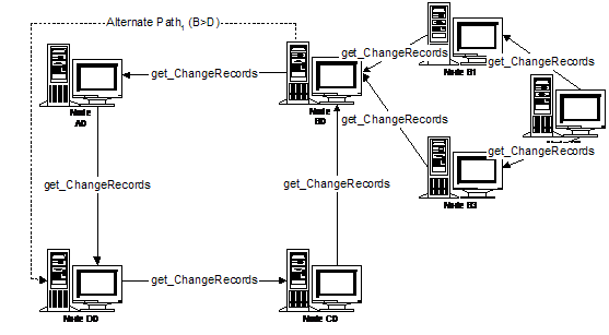
If the Communications Graph were a cycle of cycles, (e.g., if in addition to the ABCD spine, A0 was also on a cycle with A1, A2, and A3, B0 was on a cycle with B1, B2, and B3, etc.) a variation of this would be applied. When a spine node such as B0 receives a get_changeRecords request (or in the case of A, when its timer event is triggered), it handles propagation through its sub-cycle before answering the get_changeRecords request on the "spine". B0 continues propagation along the spine only after the first round of propagation completes on its sub-cycle, which means that B has received all changes from B1, B2, and B3. It does not continue the second round of propagation on its sub-cycle until it receives the second round of changes from A, which contains updates from all other spine nodes and their sub-cycles.
For a cycle, it is suggested that a backup node will be the next node in the cycle, and for added safety, the node after that as well, allowing propagation to proceed correctly even if there are node failures. Note that an incorrectly perceived node failure will not affect the correctness of the algorithm. If additional propagation is done, no unnecessary data will be replicated, although there may be additional get_changeRecords within the prescribed period.
Appendix D: Notices
Copyright © 2001-2002 by Accenture, Ariba, Inc., Commerce One, Inc., Fujitsu Limited, Hewlett-Packard Company, i2 Technologies, Inc., Intel Corporation, International Business Machines Corporation, Microsoft Corporation, Oracle Corporation, SAP AG, Sun Microsystems, Inc., and VeriSign, Inc. All Rights Reserved.
These UDDI Specifications (the "Documents") are provided by the companies named above ("Licensors") under the following license. By using and/or copying this Document, or the Document from which this statement is linked, you (the licensee) agree that you have read, understood, and will comply with the following terms and conditions:
Permission to copy, prepare derivative works based on, and distribute the contents of this Document, or the Document from which this statement is linked, and derivative works thereof, in any medium for any purpose and without fee or royalty under copyrights is hereby granted, provided that you include the following on ALL copies of the document, or portions thereof, that you use:
1. A link to the original document posted on uddi.org.
2. An attribution statement : "Copyright © 2000 - 2002 by Accenture, Ariba, Inc., Commerce One, Inc. Fujitsu Limited, Hewlett-Packard Company, i2 Technologies, Inc., Intel Corporation, International Business Machines Corporation, Microsoft Corporation, Oracle Corporation, SAP AG, Sun Microsystems, Inc., and VeriSign, Inc. All Rights Reserved."
If the Licensors own any patents or patent applications that may be required for implementing and using the specifications contained in the Document in products that comply with the specifications, upon written request, a non-exclusive license under such patents shall be granted on reasonable and non-discriminatory terms.
EXCEPT TO THE EXTENT PROHIBITED BY LOCAL LAW, THIS DOCUMENT (OR THE DOCUMENT TO WHICH THIS STATEMENT IS LINKED) IS PROVIDED "AS IS," AND LICENSORS MAKE NO REPRESENTATIONS OR WARRANTIES, EXPRESS OR IMPLIED, INCLUDING, BUT NOT LIMITED TO, WARRANTIES OF MERCHANTABILITY, FITNESS FOR A PARTICULAR PURPOSE, ACCURACY OF THE INFORMATIONAL CONTENT, NON-INFRINGEMENT, OR TITLE; THAT THE CONTENTS OF THE DOCUMENT ARE SUITABLE FOR ANY PURPOSE; NOR THAT THE IMPLEMENTATION OF SUCH CONTENTS WILL NOT INFRINGE ANY THIRD PARTY OR (WITH THE EXCEPTION OF THE RELEVANT PATENT LICENSE RIGHTS ACTUALLY GRANTED UNDER THE PRIOR PARAGRAPH) LICENSOR PATENTS, COPYRIGHTS, TRADEMARKS OR OTHER RIGHTS. Some jurisdictions do not allow exclusions of implied warranties or conditions, so the above exclusion may not apply to you to the extent prohibited by local laws. You may have other rights that vary from country to country, state to state, or province to province.
EXCEPT TO THE EXTENT PROHIBITED BY LOCAL LAW, LICENSORS WILL NOT BE LIABLE FOR ANY DIRECT, INDIRECT, SPECIAL, CONSEQUENTIAL DAMAGES, OR OTHER DAMAGES (INCLUDING LOST PROFIT, LOST DATA, OR DOWNTIME COSTS), ARISING OUT OF ANY USE, INABILITY TO USE, OR THE RESULTS OF USE OF THE DOCUMENT OR THE PERFORMANCE OR IMPLEMENTATION OF THE CONTENTS THEREOF, WHETHER BASED IN WARRANTY, CONTRACT, TORT, OR OTHER LEGAL THEORY, AND WHETHER OR NOT ANY LICENSOR WAS ADVISED OF THE POSSIBILITY OF SUCH DAMAGES. Some jurisdictions do not allow the exclusion or limitation of liability for incidental or consequential damages, so the above limitation may not apply to you to the extent prohibited by local laws.
Copyright © OASIS Open 2002-2003. All Rights Reserved.
OASIS takes no position regarding the validity or scope of any intellectual property or other rights that might be claimed to pertain to the implementation or use of the technology described in this document or the extent to which any license under such rights might or might not be available; neither does it represent that it has made any effort to identify any such rights. Information on OASIS's procedures with respect to rights in OASIS specifications can be found at the OASIS website. Copies of claims of rights made available for publication and any assurances of licenses to be made available, or the result of an attempt made to obtain a general license or permission for the use of such proprietary rights by implementors or users of this specification, can be obtained from the OASIS Executive Director.
OASIS invites any interested party to bring to its attention any copyrights, patents or patent applications, or other proprietary rights which may cover technology that may be required to implement this specification. Please address the information to the OASIS Executive Director.
This document and translations of it may be copied and furnished to others, and derivative works that comment on or otherwise explain it or assist in its implementation may be prepared, copied, published and distributed, in whole or in part, without restriction of any kind, provided that the above copyright notice and this paragraph are included on all such copies and derivative works. However, this document itself may not be modified in any way, such as by removing the copyright notice or references to OASIS, except as needed for the purpose of developing OASIS specifications, in which case the procedures for copyrights defined in the OASIS Intellectual Property Rights document must be followed, or as required to translate it into languages other than English.
The limited permissions granted above are perpetual and will not be revoked by OASIS or its successors or assigns.
This document and the information contained herein is provided on an “AS IS” basis and OASIS DISCLAIMS ALL WARRANTIES, EXPRESS OR IMPLIED, INCLUDING BUT NOT LIMITED TO ANY WARRANTY THAT THE USE OF THE INFORMATION HEREIN WILL NOT INFRINGE ANY RIGHTS OR ANY IMPLIED WARRANTIES OF MERCHANTABILITY OR FITNESS FOR A PARTICULAR PURPOSE.